IW STi Forum banner

EJ207 AVCS issue

16K views 126 replies 5 participants last post by  Eth207  
#1 ·
Ver. 8 EJ207 swapped 2002 wrx

Just finished rebuilding my motor, finally have everything running good. Just can’t get the AVCS to work.

I have CEL’s p1307 and p1309 (OCV short circuit both banks), tried clearing them, they come on 3 seconds after startup.

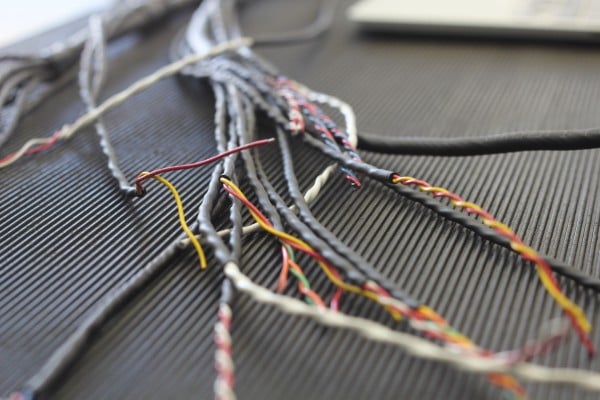
Checked all wiring/connectors, they all have continuity and everything seems to be in order, cleaned all too connections etc.

Checked/cleaned OCV, took out filters in all of the lines/banjo bolts. Tested resistance and they have ~8ohms. And put 12v to both OCV (both actuated) the entire system is as clean as can be being that I rebuilt the motor ~1500miles ago

Logged with romraider, both banks act the same. VVT angle remains at 0 (occasionally it will go to 1 or 2 when I’m letting out the clutch) duty cycle remains at 9.45%, and OCV voltage kinda jumps around all over the place

Being that CEL’s come on for both banks, I doubt it’s a mechanical issue. My best guess is maybe it has a bad ECU? It’s hard to imagine everything working except the AVCS stuff

Any ideas? I don’t have anyone to swap ECU’s with and I want to narrow it down before I go and buy a new ECU

Any help would be greatly appreciated thank you
 
#2 · (Edited)
So this is after a rebuild, presumably the heads got rebuilt: a quick sanity test to sort the mechanical aspect from the harness & ecu is to use a 5v usb power bank or 9v battery to cycle the avcs solenoids on and off, during idle, whilst logging. This will throw DTC’s you’ll need to clear afterwards, but you’ll see if the cams are advancing or not in your data logs (tuning parameters including left and right vvt angles) or on your virtual dash board.

If you have no logging perform the tests around 2krpm and you may feel the engine shake and rpm drop slightly as power is applied to a single avcs solenoid that is able to successfully change the VVT angle of its respective pulley

Because we don’t know if eg your cam pulleys and front cam caps (that contain the OCV oil supply passages) were installed correctly. Just knowing your OCV’s can actuate is insufficient when the VVT angles are inactive.

The fault modes being excessive RTV blocking oil supply to the cam pulley, preventing VVT actuation, or if the pulleys, aka sprockets were incorrectly installed on the camshafts, eg zipped up with the locating dowels not seated in their respective holes, or if they were zipped up with an impact gun whilst the camshafts were being held static, not the pulley being held static which is the correct method.


If your cam pulleys are indeed operational, follow the code specific FSM DTC procedures, or skip to inspecting your ecu for burnt components, usually in the first rows after the ecu plug tracks on the circuit board, both sides.

I’ve not heard of both AVCS ECU circuits burning out, just one side, but technically it’s possible? But then I’m not even sure of the fault mode that burns ECU tracks or components: can that fault be promoted by an overdriven AVCS system, eg integral windup from a failed OCV or sooted banjo filter etc?

For testing the harness (I didn’t peep the FSM procedures yet) I’d test it in isolation from the ECU and OCV, plug to plug, pin to pin, for resistance and voltage drop, and for continuity eg to its paired wire and or ground.
 
#3 ·
So this is after a rebuild, presumably the heads got rebuilt: a quick sanity test to sort the mechanical aspect from the harness & ecu is to use a 5v usb power bank or 9v battery to cycle the avcs solenoids on and off, during idle, whilst logging. This will throw DTC’s you’ll need to clear afterwards, but you’ll see if the cams are advancing or not in your data logs (tuning parameters including left and right vvt angles) or on your virtual dash board. If you have no logging perform the tests around 2krpm and you may feel the engine shake and rpm drop slightly as power is applied to a single avcs solenoid that is able to successfully change the VVT angle of its respective pulley Because we don’t know if eg your cam pulleys and front cam caps (that contain the OCV oil supply passages) were installed correctly. Just knowing your OCV’s can actuate is insufficient when the VVT angles are inactive. The fault modes being excessive RTV blocking oil supply to the cam pulley, preventing VVT actuation, or if the pulleys, aka sprockets were incorrectly installed on the camshafts, eg zipped up with the locating dowels not seated in their respective holes, or if they were zipped up with an impact gun whilst the camshafts were being held static, not the pulley being held static which is the correct method. If your cam pulleys are indeed operational, follow the code specific FSM DTC procedures, or skip to inspecting your ecu for burnt components, usually in the first rows after the ecu plug tracks on the circuit board, both sides. I’ve not heard of both AVCS ECU circuits burning out, just one side, but technically it’s possible? But then I’m not even sure of the fault mode that burns ECU tracks or components: can that fault be promoted by an overdriven AVCS system, eg integral windup from a failed OCV or sooted banjo filter etc? For testing the harness (I didn’t peep the FSM procedures yet) I’d test it in isolation from the ECU and OCV, plug to plug, pin to pin, for resistance and voltage drop, and for continuity eg to its paired wire and or ground.
Great advice thank you! Just put 9v to both actuators while logging and idling, VVT angle shot up to 65 and the car stumbled and stalled (Im assuming that is normal being that one head is fully advancing and the other is not?) I think we can rule out oil flow/OCV problems now? Not sure if it is relevant but I also logged OCV duty and both sides remained at 9.41% throughout the entire time, never seen those numbers change. And OCV voltage did the same thing as usual, it rapidly jumps up and down from roughly 30-1600Ma I just inspected my ECU, wasn't too sure what to look for. I inspected every inch of it closely and it looks like everything is clean and in order, no burn marks or dark spots etc As for the FSM procedures, how would I find a JDM FSM? or would a USDM dual AVCS FSM have similar info? im not too familiar with any of the other engines. Thanks again!
 
#4 · (Edited)
That’s great that you’ve ruled out the mechanical aspect, and potentially the ecu as well.

Which FSM to use might depend on your exact engine/harness/ecu/year model combo, but it couldn’t hurt to compare eg the pinout combinations on a relevant wiring diagram page from the available FSM’s.

General market FSM’s can be found at jdmfsm dot info and on sli dot net as well as a big list here:FAQ: Subaru FSM Service Manual Parts Procedures Diagnostics • club.liberty.asn.au

One aspect or FSM’s to consider is that earlier versions/years are less sophisticated than later years as regards diagnostics, so one option might be to peep the procedures for the last year of each models production, eg my04, 07, 14 etc but use the pinouts from say your year, my04. But I checked those and your DTC’s are my02-4 specific!

Sharing a driving data log here via a cloud service might be informative versus the FSM diagnostics, with tuning parameters and all of the vvt parameters, angles, duty cycles and volts, log for 20 minutes at least if feasible.


What is the engine/harness/ecu combo?
Did the setup run properly prior to swapping?
Are your engine to frame rails ground straps, and say injector riser/intake manifold grounds all intact with verified continuity? The FSM will potentially have an engine grounds map and definitely an engine grounds specific wiring diagram.

As per this post via “P1307 Subaru” google search:P1307 & P109 fault codes - ScoobyNet.com - Subaru Enthusiast Forum
 
#5 ·
That’s great that you’ve ruled out the mechanical aspect, and potentially the ecu as well.

Which FSM to use might depend on your exact engine/harness/ecu/year model combo, but it couldn’t hurt to compare eg the pinout combinations on a relevant wiring diagram page from the available FSM’s.

General market FSM’s can be found at jdmfsm dot info and on sli dot net as well as a big list here:FAQ: Subaru FSM Service Manual Parts Procedures Diagnostics • club.liberty.asn.au

One aspect or FSM’s to consider is that earlier versions/years are less sophisticated than later years as regards diagnostics, so one option might be to peep the procedures for the last year of each models production, eg my04, 07, 14 etc but use the pinouts from say your year, my04.

Sharing a driving data log here via a cloud service might be informative versus the FSM diagnostics, with tuning parameters and all of the vvt parameters, angles, duty cycles and volts, log for 20 minutes at least if feasible.


What is the engine/harness/ecu combo?
Did the setup run properly prior to swapping?
Are your engine to frame rails ground straps, and tgv grounds all intact with verified continuity?


awesome thank you, I’ll look into those links and see what I can find.

I did check continuity from the AVCS solenoid/cam sensors to the pins on the ECU connectors and everything looked good but I’m sure there’s more tests I can do.

-engine is ver. 8 ej207
-I believe the harness is original with the motor
-ECU is labeled 6A 22611AH581 I’m not sure where it comes from I just know it’s JDM.

I bought the car swapped, and I never confirmed if the AVCS was working or not, however these CEL’s are new, so it’s safe to assume there is a new issue. The CELS started coming on about 1500 miles after I rebuilt the motor, I’m now 2000miles into it.

Ej207 didn’t come with TGV’s, as for grounds, all the ground straps are hooked up, I’ve considered buying one of those grounding upgrades just to eliminate the chances of a ground fault but it should all be good, the fact that these CEL’s were not always present makes me think that something has failed, rather than something set up wrong.
 
#8 ·
John, the coolant temp tip is a very relevant consideration, in ADM cars the trigger point for AVCS activation is 60’c…

After an ECU reset, my07 GT-b’s angles sit at 3 & 9 degrees until the AVCS system recalibrates.

It’s interesting that one my02-04 owner fixed the DTC’s via the intake manifold ground, but I still haven’t found an early GD STi FSM as I’m limited to using my phone atm ;)

Easy enough to test that by running a temporary ground from a cleaned bolt on the intake manifold to eg the frame, just to rule that aspect out.
 
#11 ·
^ This for ruling out ground quickly. So long as the main ground from the harness to manifold is connected well

These are the tables I was referring to. All I was really saying was just keep it in mind
How fast do those codes trigger after a reset ?
View attachment 70311

Honestly Benny is more qualified to give ideas lol


okay that makes sense thanks for the photo! The codes come back 4-5 seconds after reset
 
#13 ·
Well now that we now at least one of the codes goes away with the makeshift ground.
Maybe try cleaning the contact points for the harness, battery terminal, and battery to frame to see if you can keep that code from coming on with the extra ground. just sand them a little

I also know for my 2013 STI there's two ground straps from the exhausts AVCS to the frame.
But I think we are talking about intake AVCS on your car ?
 
#15 ·
Well now that we now at least one of the codes goes away with the makeshift ground.
Maybe try cleaning the contact points for the harness, battery terminal, and battery to frame to see if you can keep that code from coming on with the extra ground. just sand them a little

I also know for my 2013 STI there's two ground straps from the exhausts AVCS to the frame.
But I think we are talking about intake AVCS on your car ?

Okay will do. And yes just the intake AVCS
 
#14 ·
Remember you must reset the ecu and let the engine warm up as well, and preferably log the cold start to warm, no haptic or control input, constituting an idle relearn, and preferably also logging a 20 minute off boost drive once warm.

Of course logging is optional, but you might capture your AVCS calibration process.

Since you’ve made some progress, I’d try grounding to both of the AVCS solenoid bolts, plus the intake manifold.

Or perhaps the DTC short issue refers to the RF shielding on the cam sensors? The shield must be grounded at only one end to be effective.
 
#16 ·
so I added a ton of grounds, including straight to each OCV like you said.
I warmed the car up and tested it all, as well as logged the car with the neutral position sensor unplugged, then with it jumped (I guess AVCS doesn’t actuate in neutral, so I tested the car with the circuit both open and closed to eliminate the Chances of a bad NSS, no change.)

With all these new grounds, and all connections and factory grounds cleaned extensively, i was able to get another clue on what’s going on.

So like I said, now I’m only getting a CEL for bank 2, and bank 1 OCV current now sits at 96mA, however bank 2 stays at 448, but fluctuates up and down.

I thought this change in current was random but I’ve discovered that the current on bank 2 changes when power is applied in other circuits in the car. For example when I roll down my window it goes from 448 to 415mA, or if I turn on my fog lights etc. all while bank 1 remains at a stable 96.

I’m not too familiar with electrical systems, but doesn’t that mean that bank 2’s circuit is being interrupted by another circuit? This would explain the CEL p139 “OCV bank 2 (short)”

I’m not sure how I could test the system for a short, maybe check for continuity between OCV circuit and various things in the fuse box?

As far as the cam sensor wire shielding, they are all grounded to a wire in the ECU (I confirmed the wire is correct, I forget which one exactly but I found it on other forums) I don’t know how it could be grounded from another spot? I havnt changed anything of that sort.
 
#17 · (Edited)
That’s great, remember that to test VVT angles in neutral, you’ll need to be warmed up, calibrated previously, and raise rpm gently to around 2k, on my 07 the VVT angles go to around 20’.

Again the multimeter test procedures are at the start of the FSM wiring diagrams section. If not, they’re definitely in later model FSM, eg GR+.

Testing a short is establishing continuity to another pin or ground where there should be no continuity, eg where one wires insulation is worn somewhere in the harness and allows contact to another wire, thus messing with signal sense or ground reference.

As for grounds, the two main types are chassis ground, and the ecu ground.
 
#20 ·
That’s great, remember that to test VVT angles in neutral, you’ll need to be warmed up, calibrated previously, and raise rpm gently to around 2k, on my 07 the VVT angles go to around 20’.

Again the multimeter test procedures are at the start of the FSM wiring diagrams section.

Testing a short is establishing continuity to another pin or ground where there should be no continuity, eg where one wires insulation is worn somewhere in the harness and allows contact to another wire, thus messing with signal sense or ground reference.

As for grounds, the two main types are chassis ground, and the ecu ground.

Okay so I put one probe on both pins in the OCV connector, and then with the other probe I checked for continuity to every pin in the wiring harness connectors (gray black and brown), as well as every pin in the ECU wiring and every interior/exterior fuse . Didn’t find anything out of the ordinary.

With the ignition on i back probed the connectors. my right OCV has one wire with 2v, and one with 0

the left one however had one with 0.22v and the other with 0.15, this means that the ground wire is getting power right?

I ended up back probing that ground wire, and tying a wire from that, directly to my negative terminal just to see what would happen

the CEL ended up going away fully at idle, but came back after driving. While driving, the OCV current was stable on each side (R-65mA L-33mA) and VVT from both sides would randomly jump around from 0 through 4 degrees, that’s the first time I’ve seen the left side stray from 0

The fact that there were no shorts in all the circuits I checked makes me lean on the ECU being at fault but I don’t know. Maybe there’s more to check?

I’m considering running wiring from the OCV’s directly to the ECU through the passenger firewall grommet instead of tracing the problem behind the dash
 
#23 · (Edited)
The two options for the ecu are replacement or repair.

Replacement can mean dealership level coding for security: if the ecu is coded to the security handshake set, eg key chip, cluster, bcm etc. Some generations of JDM ecu do not have this limitation, potentially.

Repair can be attempted by any business that does circuit board repairs, including some tuners (eg sick chips in Australia). Providing the AVCS circuit relevant ecu plug pinouts and the FSM ecu block diagram will help a non-automotive tech to isolate the fault.

It’s interesting that the intake manifold grounding experiments almost fixed the issue.
I have no idea why, other than reverting to diagnosis of the energised harness wires with a low amp clamp, to eg check the current flows are heading in the correct direction.

This outlier fault was discussed on the HPA site, where a ground wire that passed a continuity test, but was frayed to a single strand, caused reversed current flow.

Perhaps the auto tech you find with an oscilloscope can check that and the ecu too?

It’s potentially related to the clean and dirty aspects of ecu and chassis grounds.
It’s also important as some electrical control systems in Subaru are ground switched:


You might also perform a voltage drop test on the relevant harness wires: it’s a plug to plug, single wire test closing the loop with a multimeter set to volts, a 12v bulb and battery inline. But as you say, no change with redundant wires in place of the harness…
Unless you have say pushed or bent pins at the ecu & solenoid harness plugs.
Also always back probe any related plugs to the harness wire via the insulation, and check the ecu pins have continuity to the board. I also check all plugs and pins for integrity, discolouration/burntness, and use a little dielectric grease to promote continuity via insulation and lubrication and or to open circuit marginal connections.

There’s also checking for the spacer in the main harness plug/s at the firewall including press and shake tests, revisiting the big three and your aforementioned iwire harness kit and instructions.

Did P1307 come back?
If not, swap solenoids side to side and see what happens.
 
#24 ·
The two options for the ecu are replacement or repair.

Replacement can mean dealership level coding for security: if the ecu is coded to the security handshake set, eg key chip, cluster, bcm etc. Some generations of JDM ecu do not have this limitation, potentially.

Repair can be attempted by any business that does circuit board repairs, including some tuners (eg sick chips in Australia). Providing the AVCS circuit relevant ecu plug pinouts and the FSM ecu block diagram will help a non-automotive tech to isolate the fault.

It’s interesting that the intake manifold grounding experiments almost fixed the issue.
I have no idea why, other than reverting to diagnosis of the energised harness wires with a low amp clamp, to eg check the current flows are heading in the correct direction.

This outlier fault was discussed on the HPA site, where a ground wire that passed a continuity test, but was frayed to a single strand, caused reversed current flow.

Perhaps the auto tech you find with an oscilloscope can check that and the ecu too?

It’s potentially related to the clean and dirty aspects of ecu and chassis grounds.
It’s also important as some electrical control systems in Subaru are ground switched:


You might also perform a voltage drop test on the relevant harness wires: it’s a plug to plug, single wire test closing the loop with a multimeter set to volts, a 12v bulb and battery inline. But as you say, no change with redundant wires in place of the harness…
Unless you have say pushed or bent pins at the ecu & solenoid harness plugs.
Also always back probe any related plugs to the harness wire via the insulation, and check the ecu pins have continuity to the board.

Did P1307 come back?
If not, swap solenoids side to side and see what happens.

okay cool I’ll see if a shop can check it out. I live In Hawaii so I doubt I’ll be able to find a super sophisticated shop but we’ll see.

I think the OCV circuits internal ground in the ECU is interrupted (short to power, being that the current changes when power is applied to other circuits). because when I put a the ground wire directly into the back probed OCV connector ground wire, it almost fixed the problem. Whereas wiring straight to the ECU with brand new wires didn’t result in the same outcome. I don’t know if this makes sense but maybe that test made the ground a little better, but the fact that it was still shorting to power kept the problem present.

P1307 has not come back ever since I grounded the intake manifold better. My theory is that the 2 codes were unrelated to eachother, and the right bank was just lacking a good ground for whatever reason.


I had another one idea, being that both OCV’s should behave exactly the same, and my right circuit appears to be working. what if I just jumped wires from bank 1 to bank 2? I’m pretty sure a fault in either circuit will result in the ECU disabling AVCS entirely, but maybe I can bypass that somehow? I don’t even know why there would be 2 independent circuits if they should both function the exact same
 
#25 ·
Ok so at this point, swapping ocvs is a really basic blind test. When you ohmed the solenoids alone, did they have the same resistance?

Your idea to run both ocv’s from a single banks harness, that can work for eg tgv angle sense repurposed for external sensor use, eg wbo2, but for avcs, it’s unlikely to properly work as the system self calibrates after an ecu reset.

I guess you could try that but try eg just the solenoid power first then ecu ground, it will be immediately apparent if the control strategy is via power or ground: but will it fry the ecu further?

So just side swapping ocv’s is harmless and least intrusive.

So one aspect covered in the fsm around diag-47 is the test mode (temporarily join plugs under dash) and related system reset as mentioned in the p1307/9 etc diagnostics (top of page). These ecu level resets can be done with a dealership tool or potentially FreeSSM app on PC with tactrix or $15 vagcom kkl 409.1.

There’s a chance you can find a friendly dealer, Subaru specialist or local enthusiast to help with that.
 
#27 ·
Yes I agree that it would be kind of redundant to swap the solenoids over, as they have the same ohms and I have actuated and logged both already, I thought that's what you meant when you said to "side to side swap" what do you mean by that? do you mean connecting right side wiring to left side vice versa?


I have been using the "Reset ECU" tool in rom-raider, would that have the same effect? I have been in the process of E-tuning so everytime I put my car into test mode and flash the ECU it kinda resets in that way too.
 
#26 · (Edited)
Check this out, spiider dccd throwing those DTC’s on full lock:

So that’s an indication that this dtc is related to marginal system volts and keeping those clean and dirty grounds seperate (DCCD drawing lots of current on lock).

So pull your battery, charge it and measure volts, leave it for 24h and check the charge after the surface charge has dissipated, is it still +12.4V?

Flashing dash on key on/run means a dropped cel.

Or get your battery professionally load tested.

My car threw CPS DTC’s with a stuffed battery and very tired starter.

You’d hate to replace that ecu if you’d overlooked some diagnostic considerations 101.1!

I’ll keep googling regardless, for more clues…
 
#29 ·
Yes: literally swap the OCV’s left to right right to left.
Remember I cannot see your logs and I’m not doing the tests, so take my advice with a grain of salt, this is like a fun puzzle for me and a potentially expensive and time consuming exercise for you.
All I know is there’s no assumptions to be made in diagnostics and one needs to address the absolute basics first.

So we do know the DTC’s can be triggered by a low current situation when the car is running (eg DCCD draw), potentially on startup too.

DTC descriptions generally also refer to the affected system not necessarily the named parts.

I wanna say the battery issue is more battery current related than volts, eg if your cranking amps are low, it could cause your DTC/s.

So maybe try yet another ecu reset, a known good battery charge booster pack, or a known good battery with at least 600 cold cranking amps, and fire it up. An idle reset is probably not required on a DBC throttle, but you’ll need to let AVCS recalibrate, which might happen around that 60’c point or 10-15 minutes after cold start, around 5 minutes idle on hot start.
 
#30 ·
Some year models, the entire cluster lighting flashes, during cranking, which can indicate a bad cell in the bank of cells (lead plates submerged in battery acid) that make up the internals of a car battery.

iirc a battery with a dead cell needs replacement, especially the sealed type.

But this is more related to crank no start conditions?
 
#31 ·
Okay this keeps getting more and more confusing.

I got my battery tested at AutoZone and it checked out (I don't know how fancy their testing equipment is but he said it applies load to the battery) I also put a different battery in the car that I know is good. no change.

I took out the OCV's, I noticed the right side was drenched in oil, and the left was somewhat dry

I reset the ECU, swapped them to opposite sides and let the engine warm up:
-CEL remained the same (only p1309 for right side)
-VVT duty cycle remained at 9.41% for both sides
-OCV current stayed the same as before (however the left side no longer fluctuated when power was applied to other circuits, it just remained at 440mA while the right side was at 96)
-VVT angle was strange. Usually they are both at 0 and the right side will jump to 1 or 2 randomly, now the left side is the one jumping up like that.

Very weird how the CEL didnt change, and the oil thing is confusing me Im not sure what is going on.

again, Both OCV's have the same resistance and they both fully advanced my cam gears when I applied 9v to them during idle.

I tried thinking back to when the CEL first came up. And I am pretty sure i got the p1309 after changing out my turbo. I then pulled over and disconnected my OCV and plugged it back in, the code went away. A few weeks later the code came back, and then p1307 came too, and now here we are. I dont know if this is relavent info or not.
 
#32 · (Edited)
All info is relevant. :)
But wow, what a weird outcome so far.
If the rhs OCV wasn’t getting oil supply, the union screw/banjo bolt on the rear of the rhs head potentially having a blocked filter, one might expect the turbo to be also oil starved, meaning it should have blown up long ago.

If the banjo bolt on the rhs OCV manifold has a raised nipple on top, then that’s a filtered banjo bolt. They are interchangeable with non-filtered bolts, an aspect worth checking.

You could try a flood test on idle, pack the areas below with rags, crack the OCV manifold bolt slightly and see if oil issues forth.

Be conservative doing that bolt back up, they’re just over nipped up on the copper washer, preferably replace the washer, it’s a soft bolt, can break with too much torque.

It’s a super long shot, but I have heard of clogged oil supply tubes, also mentioned in the fsm in reference to P0011.

Your model was the (correction) second implementation of AVCS in any Subaru maybe, meaning early days, those DTC’s are apparently unique to (correction) V7& v8 STi, this is potentially part of the issue (vague diagnostics?) where they’re sometimes fixed with ground or current related fixes.

Googling continues:
Replaces V7 ecu with V8 ecu: either the shop took care of any security coding or it’s not a thing for this year Jdm ecu:

This is why a basic data log is a good first look: here the codes were in conjunction with a faulty (front?) exhaust sensor: the clue being afr stuck on stoich 14.7 afr and the engine being limited to an open loop fuel map?

This page refers to the generic obdii origins of the code (non SSM), another good reason to make a datalog:

Did you log or test your neutral safety switch?
Also your engine coolant sensor?
Brake lights all working properly?

I’m leaning towards the originating fault being an rhs bank 1 issue.

So I’d also ohm out the cam position sensor harness & plugs, inspect the cam sensor for sludge or swarf on the sensor face, check for oil in its plug etc. I have had one cmps harness resistance fail a resistance check…

Here’s one example indeed, leaking cam sensors being a known fault that can have drastic consequences: oil inundated harness…

Here’s my logging how to in case you missed it: open source and AP:

Do you have AP? Any idea who tuned it, or what tune you have?
 
#33 ·
Okay so all of my oil lines/banjo bolts do not have filters, they’re all flat bolts. I’ve checked all of them and I assume the previous owner removed all of them.

I worded it In a confusing way, but the left side was the dry side, opposite of turbo. But I think a flood test is a good idea I’ll see about that.

As for the Neutral safety switch, do you mean the neutral position switch? I’ve tried leaving it unplugged and also jumping it (I know certain years are default closed or default open so I tried both.) however in romraider, it appears the switch is working correctly.

I have not messed with the coolant temp sensor, and according to my logs it seems to be working

yes all of my lights work properly, and I do an open source e-tune with Eric from torqued performance via romraider and ECU flash


As for cam sensors, they all appear to have proper resistance, but they do have oil in the connectors no matter how much I clean them. I’ve been worried about that although I can’t help but overlook all of this info and think back to my OCV connectors. The left side did not have ground. is that not a clear indication that the ECU is bad?

we can narrow this circuit down to 3 things. OCV’s, wiring, and the ECU.

we know both OCV’s work (from applied power while Idling and seeing the advance on the log

we know wiring is good (i re-wired the entire system and it had no change.)

Doesn’t this leave the ECU left?

it could be a hundred different things. But we know that the connector does not get a proper ground from the ECU. are we beating around the bush here?
 
#34 · (Edited)
Thanks for that recap, I was about to do the same.
Time is also money, so it’s up to you if you want to try another ecu, potentially cutting to the chase.

Otherwise, and this is free to you other than time, make a datalog.

Vvt angle is in essence a cam sensor vs crank sensor calculated parameter.
So there’s minimal vvt angle to be logged, but we will see crank position as rpm, and from memory there’s maybe cam indication in the switches panel in RomRaider. Maybe Eric can advise on the subject?

If you have oil in the cam sensor plugs, this is a known fault, with oil seeping through the sensor itself via cracks in the plastic housing, also the o-rings that seat the sensor in the head: creating unmetered air vacuum and oil leaks. I upgraded to viton o-rings…

Because of the oil leaks it’s really important to check the main harness plug/s that lead to the firewall for oil contamination, as eventually the oil will get to the ecu. With new cam sensors and thorough cleaning you might get the issue under control, without having to replace or repair the engine harness: Subaru engine sensor oil leaks and loom oil contamination. • club.liberty.asn.au

It can’t hurt to follow the P0365/7 cam sensor diagnostics for the harness: the resistance checks and potentially a voltage drop test. On my car I had verified the main plug to ecu, so then I did the main plug to sensor plug, the lhs wires didn’t pass the resistance test so I back probed the affected wire and found the weak point at the first branch in the harness. I added a same gauge wire across the weak section in parallel. For sure one might expect your car to actually throw those cam sensor DTC’s, is it possible that the VVT codes override them?

As regards your banjo bolt filters, check behind the lhd drivers side (lhs) timing cover for where the OCV oil supply exits the head: this is the usual spot for a filtered banjo bolt: right where it’s hard to see and get to. If it has a nipple on the head, it might still have a filter.

But wait, we know we can discount an oil blockage because it’s been blind tested by using remote power to the solenoid during idle: full angle achieved. That’s if you’d logged VVT angle during the test and had evidence that the rising rate of the VVT angles matched each other. Say there was a partially blocked filter, you’d see a much lower rate of angle compared to a bank with good oil supply. In an extreme case of that lag, VVT calibration might struggle. It appears your car cannot make it to the calibration stage, it’s failing at the self check stage potentially.


Other considerations are things that were disconnected and reconnected during recent works, and since it’s a 20yo car maybe clean the ecu ground as well?
 
#35 ·
Many good points, ill see about finding cam position parameters via romraider, that could help out a ton.

Ill get a data log going tomorrow too

Good point about the oil flow, I also confirmed it today by doing a flood test everything looked good.

That's very interesting about oil contaminating a wiring harness I have never head of that, great write up on it too! I think it is worth looking into. I mentioned yesterday how the problem started after installing a new turbo and initially I thought there was no connection between the two, but maybe that cam sensor near the turbo was on its way out and by messing in that area it just screwed it up?

I have gotten p0365 briefly in the past, this could all be connected

Today I was messing with that same side of the engine bay (fixing a vac leak) and after I finished I took it on a test drive. I didn't see it actually happen but I noticed on romraider the "max" indication on my left VVT read 40 degrees (indicating that it reached that value) by the time I was looking at it the value was back to 0, and the right side never moved, maybe it was just a glitch. But it is interesting that working near the cam sensor seems to be effecting things

Weird how the rhs cam sensor seems to be effecting the left OCV circuit?


The sensors are a bit expensive I don't know how to test if they are functioning correctly besides checking resistance, it would be nice to see if I could log them like you were saying.


Where is the ECU ground by the way? Are you referring to the big metal block inside the ECU?
 
#36 · (Edited)
Did you find the correct cam sensor part number? Be sure to get the correct type eg 3 wire vs 2 wire iirc, try jp-carparts com maybe?

Ok it’s promising you saw a change in VVT angle, patient has a pulse, if briefly.

If you have data logs maybe upload them to datazap online and share the link, I don’t have my laptop atm.

The cam sensors are hall effect iirc, so hook them up to a multimeter and wave a metallic object over the sensor face, google will have the test specifics.

jp-carparts lists two sensors, different prices so potentially the more expensive is an update part more resistant to leakage?
You’d hope so, but always fact check any of my info here ;)

22056AA062 &
22056AA091

 
#38 · (Edited)
To make related value judgments you’d note, preferably log the maximum vvt angles achieved, the rate of change with external power off then on, and off again (attack and decay), and sustain: the powered-on test for a few minutes or more to catch any intermittent signals eg angle, duty cycle or volts, and include the harness press/shake test.

Then repeat the test also in neutral with very gentle throttle variations between 1500 & 2500 rpm, since oil pressure will be greater with rpm. Or as you mentioned previously, try to vary throttle to prevent the engine stalling as you perform the logged tests, eg get an assistant to help with either aspect of the proposed tests.

I’d then inspect the logs in MLVHD, being sure that the related parameters: closed loop, rpm, NPS, VVT L&R, AVCS duty cycle & volts, coolant temp, crank and cam switch, etc are all graphed with smoothing switched off/inactive in the app as smoothing hides dropouts.

I’d also log FBKC, FLKC, per or all cylinder roughness/misfires, knock sum, as per the logging guide.

Logging is free, apart from your time, make a gentle off boost driving log as well if safe to do so.

Eg my cars calibrated VVT angle lag was half a second or so, the lag was attack not decay, I wanna say the VVT dropouts were misfire related, eg my overdue really ash encrusted plugs, and the integral windup from partially blocked banjo filters (soot and varnish flakes) would cause the affected lhs bank to top out at 53’ as the calibration tried to catch up the lagging bank with the good (actually just better) bank.

So eg, and I hope not, a log might reveal maxed fuel trims, a persistent misfire or misfires, leading to the current hard code, or something preventing closed loop, in turn preventing AVCS operation, the DTC being a side effect. So logging casts a wider net as regards diagnostics, over just going by the DTC tests.

Oscilloscope tests are even more informative, a real time,universal to all vehicles diagnostic tool as I might have mentioned previously.

At this point replacing your ecu is still not to me 100% certain.

Also if you just went ahead and simply replaced it, did you get to the failure mode that potentially cooked it after the recent major works? Was the failure mode indeed a compromised ground that you’ve now fixed, or grounds you’ll upgrade with a big three and or iwire kit? Or is the issue something obvious we haven’t yet seen, or might see in logs?

I forgot to mention, I’ve seen the ecu ground being stated as “adjacent the ecu”: you’ll find it in the FSM cabin harness diagram/map or the grounds maps, both in the FSM wiring diagrams section. :)
 
#39 ·
ments you’d note, preferably l
To make related value judgments you’d note, preferably log the maximum vvt angles achieved, the rate of change with external power off then on, and off again (attack and decay), and sustain: the powered-on test for a few minutes or more to catch any intermittent signals eg angle, duty cycle or volts, and include the harness press/shake test.

Then repeat the test also in neutral with very gentle throttle variations between 1500 & 2500 rpm, since oil pressure will be greater with rpm. Or as you mentioned previously, try to vary throttle to prevent the engine stalling as you perform the logged tests, eg get an assistant to help with either aspect of the proposed tests.

I’d then inspect the logs in MLVHD, being sure that the related parameters: closed loop, rpm, NPS, VVT L&R, AVCS duty cycle & volts, coolant temp, crank and cam switch, etc are all graphed with smoothing switched off/inactive in the app as smoothing hides dropouts.

I’d also log FBKC, FLKC, per or all cylinder roughness/misfires, knock sum, as per the logging guide.

Logging is free, apart from your time, make a gentle off boost driving log as well if safe to do so.

Eg my cars calibrated VVT angle lag was half a second or so, the lag was attack not decay, I wanna say the VVT dropouts were misfire related, eg my overdue really ash encrusted plugs, and the integral windup from partially blocked banjo filters (soot and varnish flakes) would cause the affected lhs bank to top out at 53’ as the calibration tried to catch up the lagging bank with the good (actually just better) bank.

So eg, and I hope not, a log might reveal maxed fuel trims, a persistent misfire or misfires, leading to the current hard code, or something preventing closed loop, in turn preventing AVCS operation, the DTC being a side effect. So logging casts a wider net as regards diagnostics, over just going by the DTC tests.

Oscilloscope tests are even more informative, a real time,universal to all vehicles diagnostic tool as I might have mentioned previously.

At this point replacing your ecu is still not to me 100% certain.

Also if you just went ahead and simply replaced it, did you get to the failure mode that potentially cooked it after the recent major works? Was the failure mode indeed a compromised ground that you’ve now fixed, or grounds you’ll upgrade with a big three and or iwire kit? Or is the issue something obvious we haven’t yet seen, or might see in logs?

I forgot to mention, I’ve seen the ecu ground being stated as “adjacent the ecu”: you’ll find it in the FSM cabin harness diagram/map or the grounds maps, both in the FSM wiring diagrams section. :)

Okay so ill do a log of just cruising around, and then one of me messing with the OCV's and ill try to figure out how to post it to that site like you said.

Should I try to wire both up to one battery that way the engine isn't unevenly adjusting timing? It might be able to maintain idle that way

I have not replaced the ECU yet but I am tempted because I found one for a "good" price hopefully it doesn't sell before I decide I need it
 
#40 ·
If it’s a good price, it’s money in the parts bank… Easy to cash out if not required.

That’s the only way parts swapping is viable, if cheap parts are on hand and the fault mode won’t blow up swapped parts ;)

Yes, I did mean to wire up both ocv’s at the same time, could get fancy and extend the wires back to the cabin so you can test it solo?
 
#41 ·
Okay Good point. I was setting the car up to log and I noticed something that may leave us with a conclusion, I will try my best to word this correctly.

Both OCV connectors were conected, I put pins in each wire in the connector and attached Alligator clips to each side. (R/L red and black matching on each side, making sure to keep them from contacting eachother)
Unaware of the correct polarity, I start on the left OCV and attach the 2 wires to 9v, I hear a loud click (OCV Actuated).
I then swap the wires around to reverse polarity, I hear the same loud click.
Then I grab the right side OCV wires, I put them on the battery, I hear a weak click (Initially this made me believe the OCV was bad)
I swap the wires around, nothing actuates.

To summarize this part of the test:
The Left OCV strongly actuates regardless of polarity and the right only actuates one way, and it is weaker sounding.


I then bridge both wires together and put them to the battery, nothing actuates.
I switch them around, nothing actuates.

The OCV's would not actuate in any way, when bridged.

Then I unplug the OCV wire connector from the ECU (the circuits are now only connected to my 9v). I do the same tests...
I start with the left side: just like before, the OCV strongly actuates for both polarities.
I then do the right side: to my surprise, both polarities result in a strong actuation.
I then bridge the wires: Both OCV's actuate at the same time for both polarities.

This, as well as my wiring test, and the fact that one of the connectors isn't getting a good ground seem to point at a bad ECU.
....
here's the weird part. Im still only getting a p1309, Left side fault. these tests seem to show a fault in the right side...

Also if you remember, when I swapped OCV's I started seeing the Left side jumping angle 0-1 degrees and the right side remained at 0.... this was the oposite before I swapped them over


Now whats even weirder, I was logging a cruise log, while accelerating, My left side OCV went to 80 something degrees. I have never seen numbers this high, very weird.


What do you think about this
 
#42 · (Edited)
Might be a good idea to graph the log to get that maximum advance angle? Primarily so I can google it.
Eg is this something anyone else has experienced? Is this the cam pos fault we want to see?

Apparently vvt angle can be affected by oil pressure alone?

As an aside and in reference to engines with exhaust AVCS on non exhaust avcs ecu’s someone proposed an external avcs controller (edit this later)

Did each OCV see 9v or 4.5v? Eg was it wired in series or parallel?

I’d have to see the log for the circumstances, and was the ecu reset prior? Eg is that an attempted recalibration?

You’re brave doing the test piggy backed on the ecu, if you compare the results to the wiring diagrams, the idea the ecu tune calibrates and controls two seperate channels, you may gain insight.

Again with parts swapping OCV’s, if you can find a known good item to swap in, it could be informative. A local enthusiast tore down his failing OCV’s, the fault mode being galling wear on the actuator shaft. As far as I know, the solenoid is similar to a linear motor, which might explain that they work with reversed polarity.

It would be interesting to test the OCV’s using power to either pin and the OCV shell as ground, with a multimeter on volts and or resistance inline: is the shell isolated or not?

I guess you could extend your previous test by bridging one channel of both ocv’s then the other.

Hopefully you’re logging all the tests?
That’s going to be really interesting to see.
You can also share via google drive, or Dropbox, eg try drop the .csv in this folder: Eth207 my02 04 jdm swapped hawaii
Uploading to data zap is really easy after iirc registering, then anyone can graph on the site or DL the files.
 
#43 ·
Might be a good idea to graph the log to get that maximum advance angle? Primarily so I can google it.
Eg is this something anyone else has experienced? Is this the cam pos fault we want to see?

Apparently vvt angle can be affected by oil pressure alone?

As an aside and in reference to engines with exhaust AVCS on non exhaust avcs ecu’s someone proposed an external avcs controller (edit this later)

Did each OCV see 9v or 4.5v? Eg was it wired in series or parallel?

I’d have to see the log for the circumstances, and was the ecu reset prior? Eg is that an attempted recalibration?

You’re brave doing the test piggy backed on the ecu, if you compare the results to the wiring diagrams, the idea the ecu tune calibrates and controls two seperate channels, you may gain insight.

Again with parts swapping OCV’s, if you can find a known good item to swap in, it could be informative. A local enthusiast tore down his failing OCV’s, the fault mode being galling wear on the actuator shaft. As far as I know, the solenoid is similar to a linear motor, which might explain that they work with reversed polarity.

It would be interesting to test the OCV’s using power to either pin and the OCV shell as ground, with a multimeter on volts and or resistance inline: is the shell isolated or not?

I guess you could extend your previous test by bridging one channel of both ocv’s then the other.

Hopefully you’re logging all the tests?
That’s going to be really interesting to see.
You can also share via google drive, or Dropbox, eg try drop the .csv in this folder: Eth207 my02 04 jdm swapped hawaii
Uploading to data zap is really easy after iirc registering, then anyone can graph on the site or DL the files.


Okay Ill try to log more tonight, I put my cruise log with the 80 degree left side VVT thing in that dropbox, im not sure if it worked or not, and I wasn't sure how to find "closed loop" so I just selected CL/OL fueling and closed loop fueling. I also couldn't find the cam or crank sensor stuff I hope its still valid. Also youll notice my gear parameter reads gear 6 when in neutral. I am pretty sure this is normal because I have seen other guys on the forums relate to that.


Each OCV wire was placed on he same 9V battery, I guess you'd call it parallel?

What are your thoughts on my tests? doesn't this kind of prove that the ECU is at fault? the OCV wouldn't actuate as good or with both polarities when plugged into the ECU
 
#45 ·
I wasn't able to get the drop box to work so I uploaded them to data zap. I uploaded 2 sets of logs, cruise and idle. there are 3 cruise logs and 2 idle logs, the file name will describe what is happening in the log ex: OCV's connected vs disconnected.

Idle Logs

Cruise Logs

Hopefully those links will work

For whatever reason, the AVCS on the right side decided to be fully operational during my test drive, for the first time all 3 parameters were moving around the way they should (I think)

One notable point, when I was applying 9v to the OVC's during Idle, they individually actuated good, but when applying power to both, 9v would not do it. So I just went to the 12v battery and then they were able to both actuate at the same time, interesting.....
 
#46 · (Edited)
On the latter note, the OCV’s may have been getting 4v each from the 9v battery which is probably at the lower end of the actuation threshold?
Ok, in the logs we’re looking for out of normal range data, and data anomalies.
So I can see your long term fuel trim, af learning, is heading out of acceptable range negative.
But that’s a state of tune, usually a vacuum leak, issue, it’s not appearing to affect knock learning, at least off boost during cruise.
One anomaly I see is the rpm signal diving to zero after a quick peak, I see that as an anomaly: further investigation required, eg start by checking the integrity of the crank pos sensor plug: visual inspection, back probe the pins to the harness wires immediately after the plug and or at the ecu, use some dielectric grease in/on the pins, make sure the pins are clean on the sensor and the plug sockets aren’t over rounded, look for corrosion etc.

Then I’d repeat the cruise log with eg a 9v battery on each OCV, we want to check the cam sensors vs crank sensor, rpm & vvt angles whilst driving around, with the OCV’s pinned to max angle.
Generally vvt angle is high during cruise, so hopefully the car can get moving in that condition.
If not do the test warmed up in neutral using the vary rpm test method I already mentioned. We want to rule out issues with the crank & cam sensors before committing to say a new ecu.

You might address the crank sensor plug checks prior to these tests.

I’ll have access to my laptop next week so I can graph the logs with MLVHD, so no rush, the engine does not appear to be in danger, off boost, at this point.

Bear in mind I’m peeping those logs on my phone so results may vary, the rpm glitch is just after halfway through the cruise log, I’ll try upload a screenshot… It might be just a gear change but the cruise/idle log with actuated vvt is still something worth doing to see if the cam signals are steady.
 
#47 ·
Interesting. Maybe my crank/cam sensors are all bad, ill see about doing the test while driving hopefully it runs okay. It’s not dangerous for the engine right? It does stumble at idle pretty bad when they’re at max value

I forget what exactly it was, but I was looking at the OCV currents on the cruise log and it seemed to be dropping up and down at weird times.

Also if you’ll remember they use to stay at 9.41% for the majority of this testing. I noticed randomly while driving, both left and right would shoot down to 9.41% for a little bit, like it was wanting to go back to the way it was before, when none of it worked

it’s so strange how the right side just snapped out of it and decided to work

Image

heres A picture of my OCV’s I just thought it was weird how one is less stained, but I guess the swap test proved no change from each side
 
#49 · (Edited)
Let’s say you get this sorted, eventually, there is a basic set of logging parameters used for tuning and keeping an eye on the state of tune. It’s a good idea to save that specific profile in romraider or btssm apps, as using that profile makes comparing multiple logs in eg mlvhd app easier.

For diagnosing a specific issue, save that profile under a different name (or vehicle in btssm) till you get to the issue, then revert as above.

The preferred list is in my logging faq, eg Eric’s set with a few added parameters, see the paragraph
Logging Parameters for H4DOTC:
From Torqued Performance
Again that’s more for day to day logging after this issue is fixed.


Loooking at the cruise log, I didn’t see the rpm scale at the left side, I think what I saw as an rpm glitch is a normal gear change.

But try the cruise log again with remote power to the OCV’s, when I use mlvhd, maybe I’ll be able to see any cam sensor faults as vvt dropouts.

For this diagnostic, we can see ol/cl is active, you have coolant temp active, which leaves crank switch, cam switch/es, neutral switch, brake switch (in the RR switches tab) as some sanity checks to log or check live (although surely these would throw DTC’s: can’t hurt to check anyway.
 
#50 · (Edited)
Sure is interesting that with the dtc active, vvt inactive, lhs OCV current is active, rhs not. Does this represent the short referred to in the DTC diagnostics?

Gear position is a bit glitchy, but this is ecu estimated:Gear Position ESTIMATED (Gear Position) -> Current estimated gear position as determined by the ECU. This value is estimated based on RPM and vehicle speed.

So that could be a clue… I’m not sure to what extent datazap smooths data, but even a little will negate dropouts, looking again vs known good data next week ;)
 

Attachments